Flexray Slots
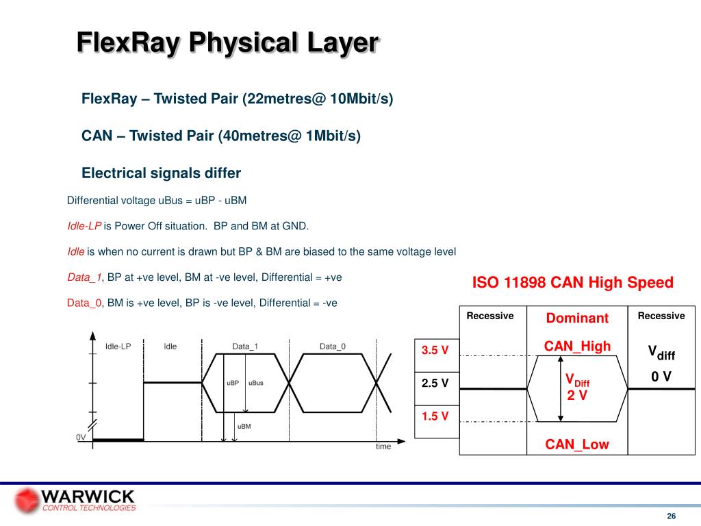
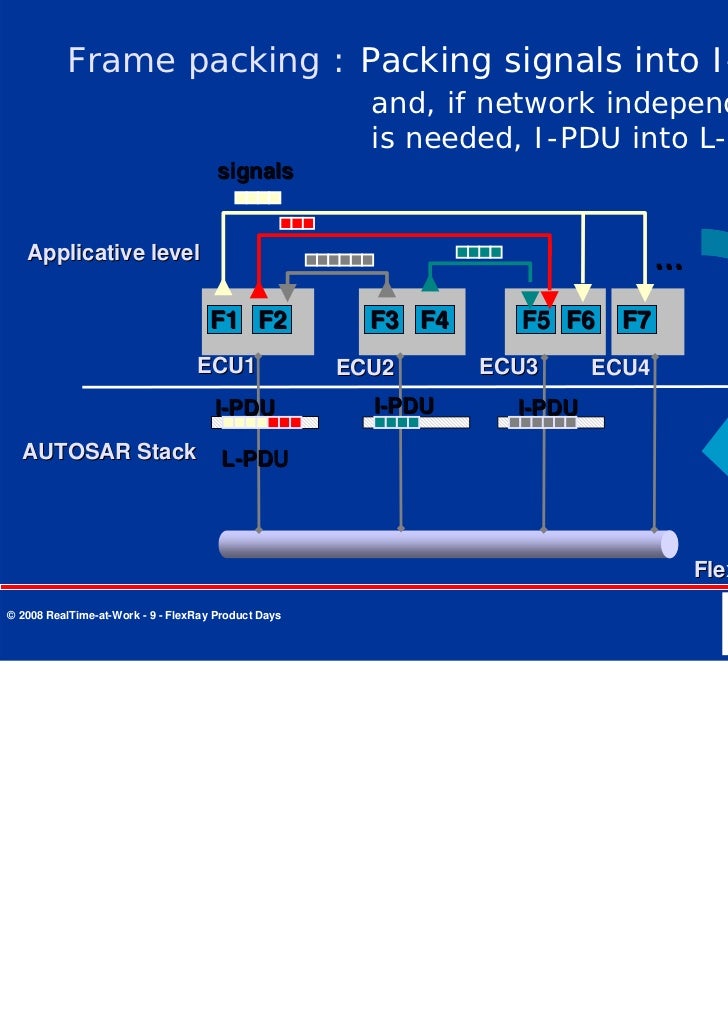
FlexRay™ Protocol Controller Key Features Customer Benefits Highlights E-Ray module performs communication according to the FlexRay™ protocol specification v2.1 E-Ray module supports data rates of up to 10 Mbit/s on each channel. Configuration of up to 128 message buffers Filtering based on slot, cycle, and channel value. The FlexRay Interface does not directly access the FlexRay hardware (FlexRay Communication Controller and FlexRay Transceiver), but by means of one or more hardware-specific Driver modules. In order to access the FlexRay Communication Controller(s), the FlexRay Interface. FlexRay: A Time-Triggered Protocol for Drive-by-Wire Applications Syed Masud Mahmud, Ph.D. Electrical and Computer Engg. Wayne State University Detroit MI 48202. FlexRay cycle, imposing a system-based synchronization. In this work, we propose a different approach to deal with the design of the static segment. Basically, we evaluate the number slots required by each FlexRay node, using traditional response time analysis (RTA) techniques. Therefore, the number of required slots will be. FlexRay Protocol Conformance Test Specification DISCLAIMER This specification and the material contained in it, as released by the FlexRay Consortium, is for the purpose of information only. The FlexRay Consortium and the companies that have contributed to it shall not be liable for any use of the specification.
Arm® Processors
Arm® MCUs
Power Architecture® Processors
All Processors and MCUs
Audio
Interfaces
Peripherals and Logic
Power Management
Sensors
RF
RFID/NFC
Security and Authentication
Wireless Connectivity
Browse all products
Product Information
Application-Specific Products
Automotive
Mobile
Industrial
Smart City
Smart Home
Communication Infrastructure
Enabling Technologies
NXP Designs
Technical content and expertise to help jump start your design and get you to production faster.
Start your designSoftware
Download our latest development and embedded software solutions.
Development Boards
Expedite time-to-market with our extensive lineup of development kits.
Designs
Jump-start your design with proven hardware and software solutions.
Documentation
Get the latest specifications in our technical documentation library.
Training
Further your technical expertise with online and in-person instruction.
Commercial Support and Engineering Services
Get comprehensive paid support to fast-track your product development.
Support

NXP Community
Design ideas, demo videos, quality answers. Connect with NXP professionals and other knowledgeable designers ready to help.
Training
Design Resources
Software, documentation, evaluation tools. The resources to build comprehensive solutions and accelerate your time to market.
Access our design resource libraryOur Company
News and Media
Investor Relations
Contact Us
Events
Careers at NXP
We're always looking for passionate and talented people to work with us.
Flexray Slot Id
Join our teamThe purpose of this test is to verify the integrity of the FlexRay networks by checking the mirror image nature of the signals and the coincidence of the edges.
How to perform the test
View connection guidance notes.
- Use manufacturer data to identify and access FlexRay high and FlexRay low circuits. (access is usually available at the multi-plug connector on components controlled by FlexRay, door locks, window motors etc.).
- Connect PicoScope Channel A to FlexRay high.
- Connect PicoScope Channel B to FlexRay low.
- Minimize the help page. You will see that PicoScope has displayed an example waveform and is preset to capture your waveform.
- Start the scope to see live data.
- Operate the system you have accessed.
- With your waveforms on screen stop the scope.
- Use the Waveform Buffer, Zoom and Measurements tools to examine your waveform.
Note
The BNC-to-4-mm cables that are used for normal signals are not suitable. For high-speed signals like those used on the FlexRay network, you must use high-speed probes.
Example waveform
Waveform notes
The above FlexRay waveform is a detail zoom of the FlexRay message and allows the individual state changes to be viewed. This enables the mirror image nature of the signals, and the coincidence of the edges to be verified.
Here we can see clearly that the signals are equal and opposite, and that they are of the same amplitude. The edges are clean and coincident with each other. This shows that the FlexRay network is enabling communication between the nodes and the FlexRay controller unit. This test effectively verifies the integrity of the bus at this point in the FlexRay network, and if a particular ECU (node) is not responding correctly, the fault is likely to be the ECU itself. The rest of the bus should work correctly.
It may be necessary to check the condition of the signals present at the connector of each of the ECUs on the FlexRay network as a final check. The data at each node will always be the same on the same bus. Remember that much of the data on the network is safety critical, so DO NOT use insulation piercing probes on FlexRay lines!

Further guidance
Flexray Slot
FlexRay is a fast, deterministic and fault-tolerant bus system for automotive use.
The FlexRay® protocol answers that demand with a high speed, deterministic and fault tolerant communications technology. Designed specifically for in-vehicle networking, FlexRay won't replace existing networks, but instead it will work in conjunction with already well-established systems, such as the controller area network (CAN), local interconnect network (LIN) and media oriented systems transport (MOST).
An in-vehicle network with FlexRay serving as the backbone provides determinism for engine control and fault tolerance for steer-by-wire, brake-by-wire and other advanced safety applications.
In FlexRay, the cycle period is divided into two parts: One static, for time-critical messages, and one dynamic, for less important messages. The static part is time-triggered whereas the dynamic part is event-triggered. For example, a node transmitting messages to the brakes would be in the static part whereas a node transmitting information to the audio system would be in the dynamic part.
FlexRay - compared to CAN - offers a significantly greater bandwidth of 10 Mbit/s.
Disclaimer
This help topic is subject to changes without notification. The information within is carefully checked and considered to be correct. This information is an example of our investigations and findings and is not a definitive procedure. Pico Technology accepts no responsibility for inaccuracies. Each vehicle may be different and require unique testsettings.
Suitable accessories
Help us improve our tests
We know that our PicoScope users are clever and creative and we’d love to receive your ideas for improvement on this test. Click the Add comment button to leave your feedback.
1 comment Add comment
I do not see the configuration of the high speed probe as being at all suitable for automotive use. This is a hand held lab scope probe, might be electrically suitable but not physically suitable